Grabbing LCD display content on an air quality monitor
A few years ago, I bought a simple air quality monitor. It’s not “smart”, and the data is simply shown on a LCD display. I went on a small adventure trying to convert it to a connected device, and extract the data so that it could be plotted on a graph (e.g. to tell the effectiveness of an air purifier).
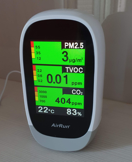
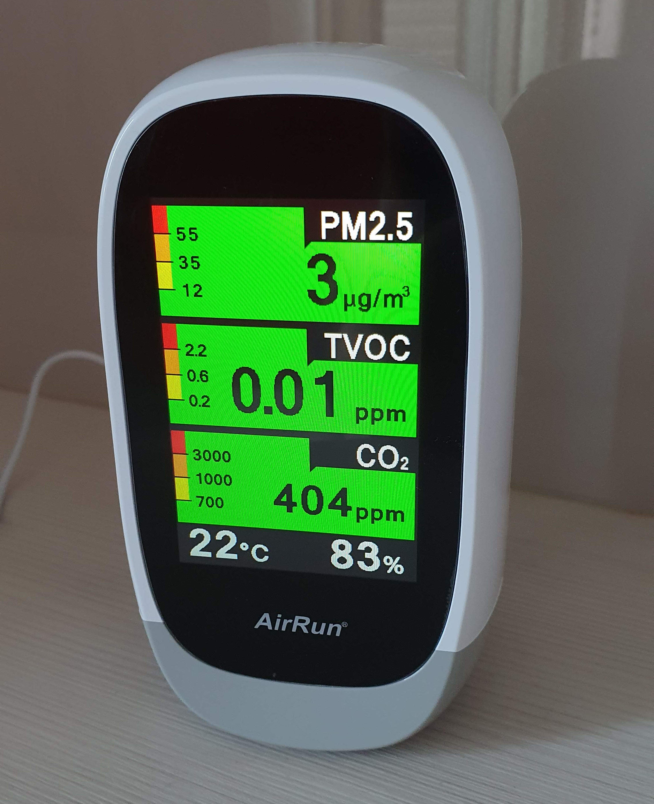
Of course, the easiest approach would be to buy a new sensor (that same manufacturer has one with Wifi enabled nowadays), or even roll your own with an ESP32 and parts. But in the spirit of my vibe-EEing experiments, I thought I’d have a bit of Claude-assisted fun.
RAM dumps via ICSP
I dismantled the air quality monitor, found out it’s based on a simple PIC32MM. My first hope was to be able to use the ICSP (In-Circuit Serial Programming) debugger and repeatedly dump the RAM content to find where and how the air quality data is stored.
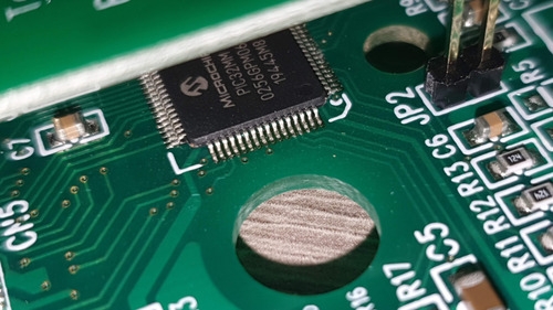
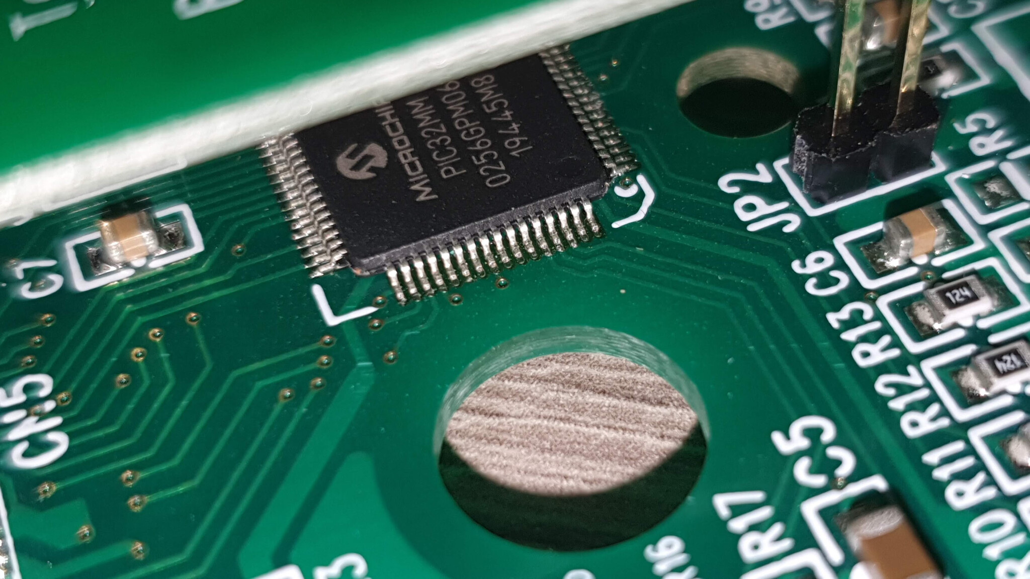
The PCB is only 2 layers, so it’s reasonably easy to trace pins from the MCU to headers. The programming header is 5 simple pins (MCLR, VDD, GND, PGED, PGEC).
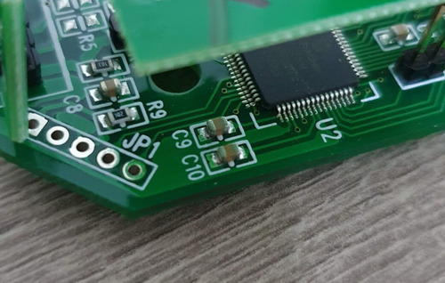
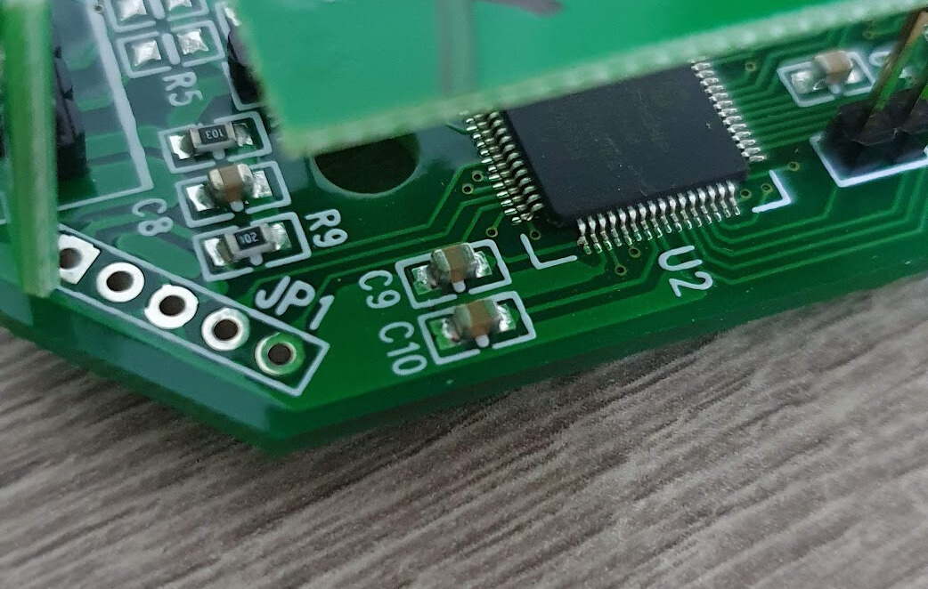
I did not have a PIC32MM programmer on hand, and some good packages exist for RP2040 (kiffie/pic32probe), but I only had some ESP32-C6 boards available. So I just ended up vibe-coding a programmer in Rust/embassy for that board. It was quite interesting to see Claude struggle with the spec, and it ended referencing the pic32probe code A LOT. Working code is here, not that it’s particularly worthwhile.
That idea, however, quickly died: the device is code-protected. In this mode, it is not possible to read back the firmware (not my plan anyway), nor use the debugger. The only thing I could have done is to completely reflash the chip, not what I wanted to do here.
LCD grabbing
The next idea is quite a bit more advanced (and where it gets really fun!). Now that I know the MCU is a simple PIC32MM, with only 32 KB of RAM, it’s clear that it could not hold a full framebuffer (so the LCD has to be somewhat smart), and that signals have to be reasonably low speed.
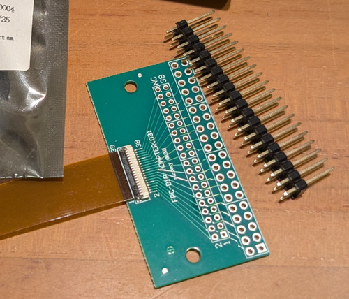
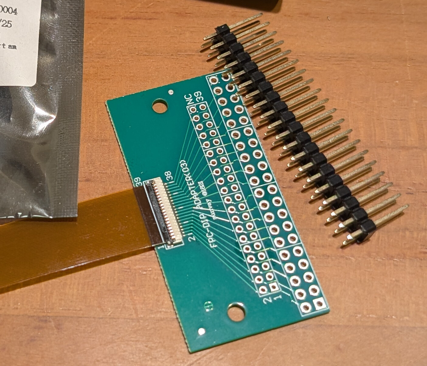
I started probing the LCD connector. It’s a bit of a headache to count pins on 2mm pitch connector or FPC and set the multimeter/oscilloscope probe correctly, so I found a 39-pin 2mm FPC to 2.54mm DIP adapter on Shopee to make my life easier, and ended up with the following pinout guess:
- 1 GND
- 2-17 pulses
- 7-12 also pulses, but sometimes lingering at 3.3V
- From 11-17, lower frequency? Slower high/low pulses
- 18-19 GND
- 20 high
- 22 pulses – very regular, I wonder if this is some clocking?
- 500ns down pulses every ~1.5us
- 23 short pulses? End of something?
- ~500ns low pulse every ~10us
- 24 very short pulses, frequent
- ~200 ns low pulses every ~1.5us
- 33/35/36/37 3.3V (all shorted confirmed)
Based on this information, and a bit of further probing1, Claude helped me figure out this is probably an ILI9488 or ST7796S chip (or similar), using a 16-bit 8080 parallel MCU interface. Those are “smart” displays that take in partial updates commands, making them well suited to be driven from a small MCU like the PIC32MM.
The final Claude-authored notes about the display and pinout are here: display_notes.md.2
RP2350-based grabber
After a bit of back and forth with Claude, I ended up getting a Raspberry Pico 2 W board for further experiments. The RP2350 has an excellent programmable I/O (PIO) controller that makes it very easy to prototype: no fixed trigger pin assignment, and it’s easy to adjust edge and timing.
I told Claude to write a RP2350 firmware in Rust/embassy, and I played smart hands for the AI. I connected the pins as it advised, pressed the bootloader/reset buttons as instructed. After a while, got a bit tired of being reduced to an assistant button presser for the AI, so I asked Claude to write functions to reset the board to bootloader mode, to make it able to reflash the firmware unattended.
And then basically watched it experiment (under some supervision). One of the challenges was to identify the purpose of pins 22/23/24, and the exact capture timing. The key here is WR (pin 24) that latches the data bus pins 0-15 on an edge. The DC (pin 23) is also quite important, as it is active at the beginning of each LCD command. A challenge with the DC (pin 23) is that it seemed to transition close to the WR edge. A small delay in the PIO capture code helped.
let prg = pio_asm!(
    ".wrap_target",
    // Falling-edge sampling. After WR transitions high→low we
    // re-check that WR is actually still low — filters any
    // spurious mid-cycle dips on WR (e.g. ringing on the
    // rising edge of the previous pulse) that would otherwise
    // produce a phantom sample.
    "start:",
    "    wait 1 gpio 18", // 18: WR
    "    wait 0 gpio 18 [2]", // short delay, then recheck WR
    "    jmp pin, start", // pin: WR
    "    in pins, 18", // 0..15 == DB0..15, 16: CS, 17: DC, 18: WR
    ".wrap",
);
All of this was figured out with a mix of reading the spec, and trial and error. I’m still not convinced that using the falling edge + short delay is correct, but that seems to be what works best. I’ll also say that watching Claude struggle was sometimes frustrating, it often gets stuck in reasoning loops, but it seemed to be possible to make it escape those with (sometimes aggressive) nudging.
The final RP2350 firmware is in this folder.3
Host-side display app
As part of the experiments, I asked Claude to write an LCD command parser, first to debug the capture visually, and then to actually write code to grab the data. I gave complete freedom to Claude, and it picked eframe for this.
The whole setup looks like this: an FPC adapter tapping the LCD signals, a Pico 2 for capture, and decoding live on the laptop.
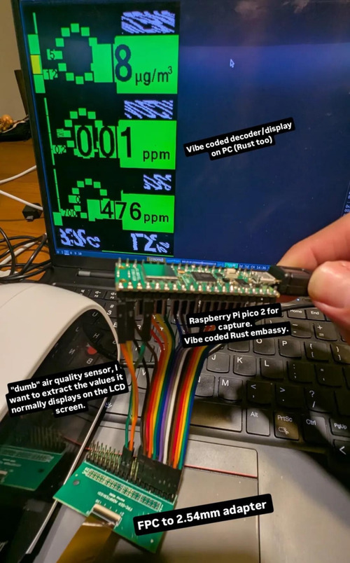
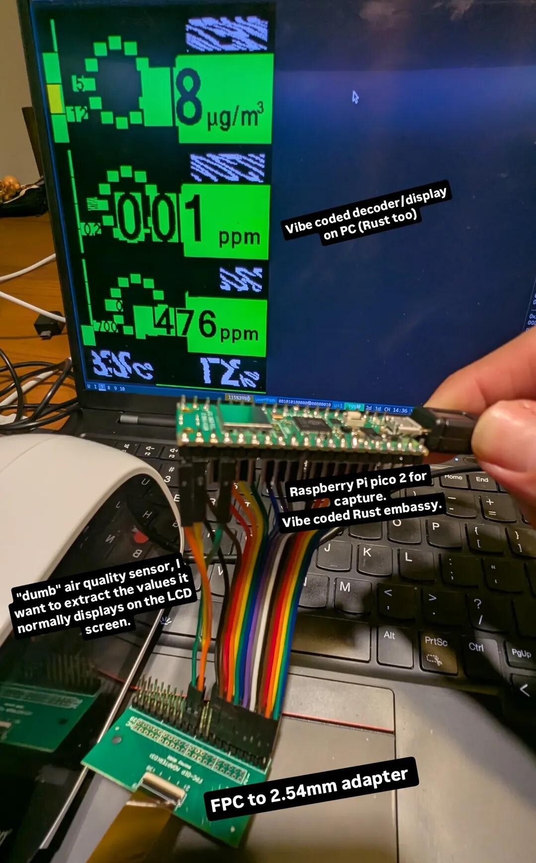
I must say the result feels quite magical:
The right-side video perhaps gives the best picture of how the display is updated. There are two things to watch out for:
- Single digits are updated at fixed positions using partial rectangular repaints, and it’s only on reset that the display is fully repainted. For example, when the PM2.5 value changes from
12to15, only the unit digit5is repainted. This means that we cannot be certain of the complete value unless we grab data from boot time. - We also need to be careful when multiple digits are updated, e.g. a temperature change from
30to29may be briefly displayed as20.
From there, converting the displayed information to numerical data is reasonably easy and completely deterministic: There are only 10 glyphs (digits 0-9) of 3 different sizes, as well as a decimal separator for TVOC data. We can simply grab all possible digits, ask Claude to classify them (or just do this by hand). Then, at runtime, we can just compare glyphs pixel by pixel to the references.
The code of the host is here. It also relies on other workspace crates as they ended up being reused later on embedded platforms.
That’s it for now. In the next posts I’ll look a bit at bandwidth issues, data compression, design of a hybrid ESP32+STM32 platform, Claude-assisted PCB design, and finally some home assistant integration.
-
I later ended up finding the exact model on Alibaba after disassembling the whole unit, which required unglueing the display. I only did that because I accidentally broke the flex, and needed to order a replacement unit, but that’s another story. ↩
-
Like all the other markdown documents I link here, they are Claude-generated, and the content might be left in some slightly outdated shape: I made no attempt to clean anything up. They should still be human readable though. ↩
-
Similar note, the firmware code is a fairly quick-and-dirty semi-vibe-coded experiment, it works for me, but it’s not necessarily in a shippable or secure shape. ↩