From zap! to PCB
This is part 2 of my zapping adventure, part 1 is where I describe goals, experiments, and design.
Once I confirmed the detection circuit and software works, I wanted to shrink the design, and make it more “professional”. I never designed a PCB in my life, so this was a good opportunity to start!
I used KiCad to draw the PCB, based on the schematics in the previous post, and included the detection antenna directly in the PCB. The files are available on github.
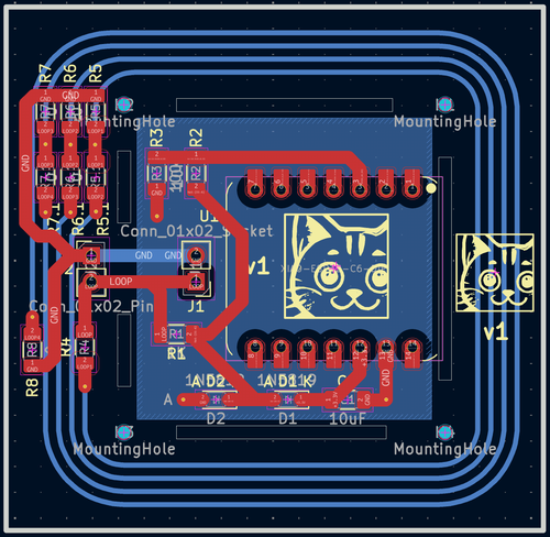
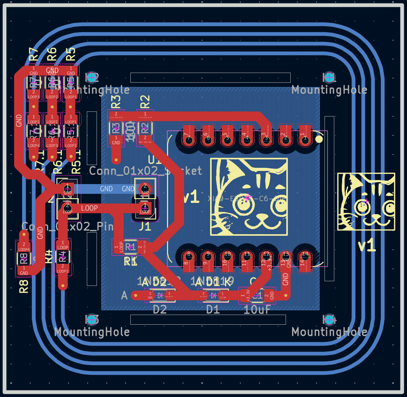

I wasn’t sure if the ESP32 board would be happy to sit so close to the EMI spike, so I designed the PCB in a way that the antenna could be separated from the detection circuit and ESP32 if needed.
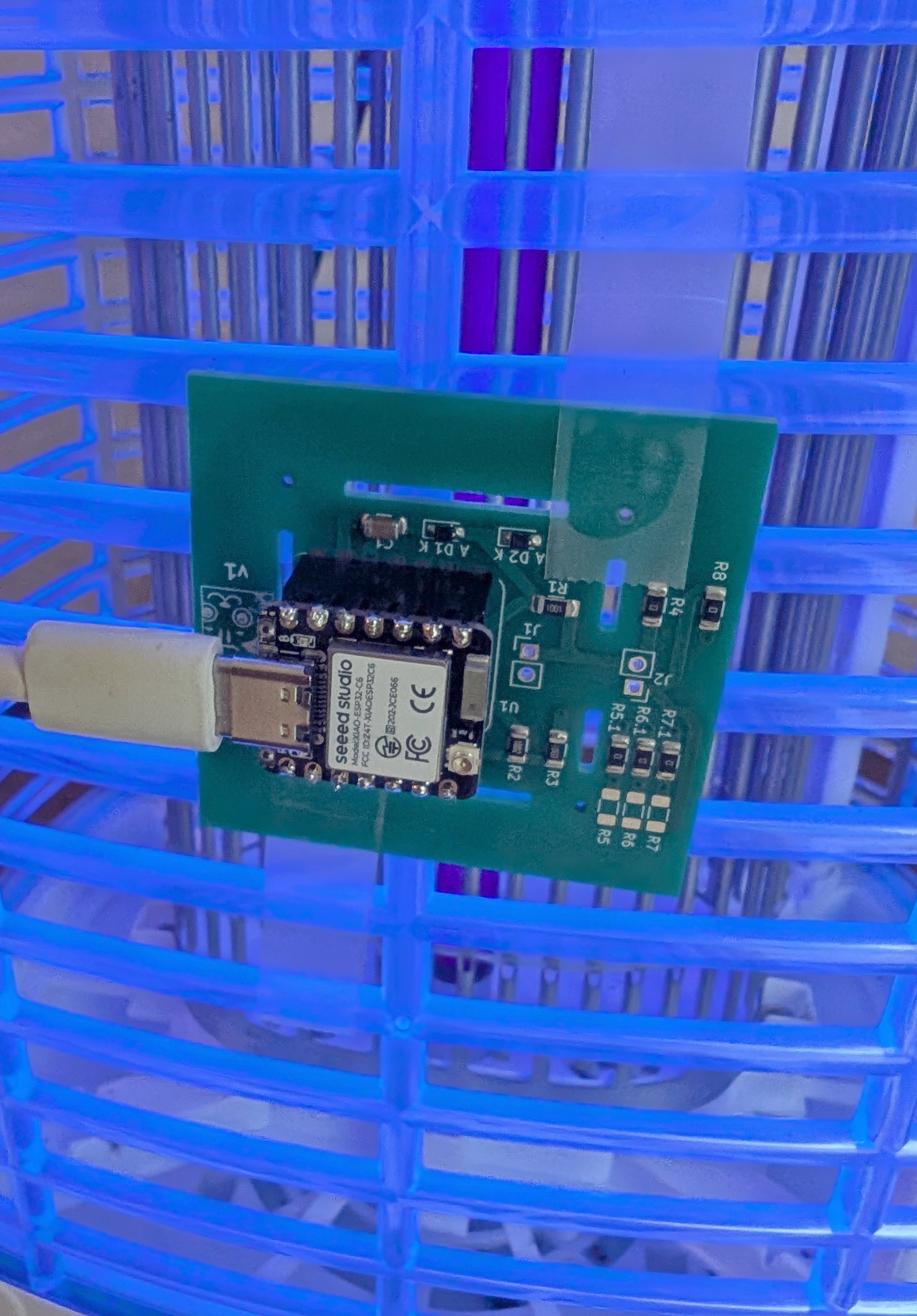
To reduce complexity, cost (and avoid import regulations issues), I didn’t want to directly manufacture a PCB with ESP32 on board. So I simply included the through holes to solder a header on the board and plug in an ESP32-C6 Xiao board – I also included pads if I wanted to solder the Xiao board directly using castellated edges.
Finally, I also added some 0-ohm resistors to the antenna to make it possible to shorten or lengthen it, as I only did a very rough estimate of the inductance.
Manufacturing
I went for JLCPCB here, as it’s incredible value for money, especially when including shipping to Taiwan where I’m located.
I won’t go into the details of JLCPCB gotchas and best practices (lots of resources online and I found it fairly easy to do trial and error on their site before manufacturing), but just 3 things to note:
- I used the DRC rules by labtroll.
- To generate Gerber files, BOM, and placement files, I used the wonderful Fabrication Toolkit by bennymeg.
- If you want to specify tooling hole locations, use the “ToolingHole” footprint installed by the plugin above.
Cost breakdown, with coupons applied:
- 2.00 USD for PCB manufacturing (2-layer) – 5 pieces
- 1.00 USD for PCBA (assembly) – 2 pieces (out of the 5)
- 2.88 USD for shipping
- 0.00 USD customs fee
So, a total of 5.88 USD, and it took 10 days from me sending the order to receiving it – that’s actually much longer than expected, had some slight issues with the shipment that I won’t get into here.
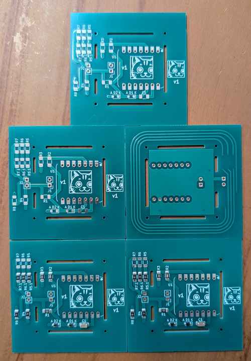


As you can see, 2 of the 5 boards are assembled. I did this to keep the weight super low to save on shipping (the components themselves, and assembly, are essentially free with coupons), and the components are big 1206-size so I could solder them by hand if necessary.
And, finally, a video, similar to the one on the previous post. I’m using a screwdriver (just after turning off the tower) to “emulate” a mosquito. The detection is shown by the LED blinking:
Looks like it’s just working, the loops are long enough, and the ESP32-C6 does not mind the EMI spike.
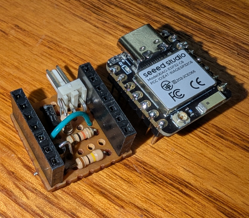
Addendum
Just for fun, before making a PCB, I made a tiny stripboard version of the detection circuit. I won’t show the back side with my terrible terrible soldering.